
New Products
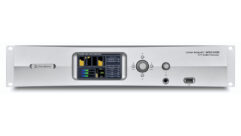
EAW UXA4416 DSP Power Amplifier — A Mix Product of the Week
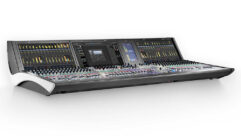
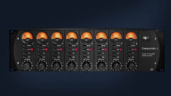
This week, the folks at EAW unveiled the latest addition to their UXA Series of power amplifiers, the UXA4416.
Update your browser to view this website correctly. Update my browser now
This week, the folks at EAW unveiled the latest addition to their UXA Series of power amplifiers, the UXA4416.

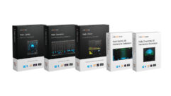
Pure:unmask is the latest plug-in in Sonible’s “Pure” series of AI-powered processors, designed to automatically duck a track
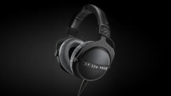
beyerdynamic has shipped its DT 770 Pro X Limited Edition headphones, first announced at NAMM 2024.

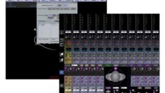
At the 2024 NAB Show, Sony showcased integration of the Waves Cloud MX audio mixer with its M2L-X live production switcher.

Mix is pleased to announce the recipients of the 2024 Best in Show Awards at the NAB Show.
DiGiCo's latest update adds Pulse upgrade access, new Klang KOS 5.5 integration, new immersive platform capabilities and more.
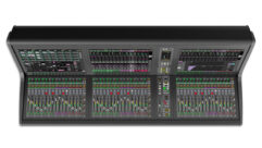
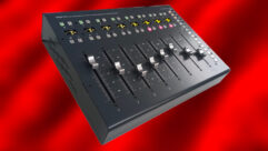
Solid State Logic launched a compact control solution for the System T production platform, the System T S400 console, at the 2024 NAB Show.
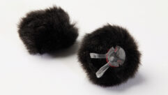
DPA Microphones introduced its new AIR1 universal miniature fur windscreen for round, omnidirectional headset or lavalier microphones.
Waves announced its SuperRack LiveBox hardware server and introduced the latest version of the SuperRack SoundGrid plugin-processing system.
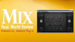
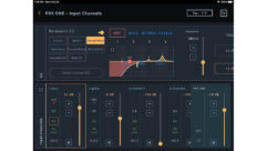
Our reviewer finds BX_Enahncer to be a powerful, channel-strip-like plug-in with saturation and sculpting.
Blackmagic Designs DaVinci Resolve 19 includes a variety of new audio features, some powered by AI.
Eclipse Audio's FIR Designer 4.2 adds Auto IIR, speeding up the IIR-filter-based equalization for loudspeakers and systems.
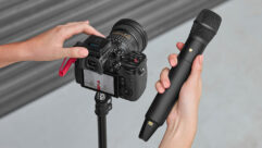
Røde has launched the Interview Pro, a wireless handheld microphone for use with the company’s wireless systems.
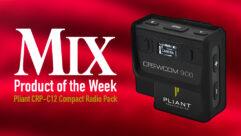
The CRP-C12 from Pliant Technologies is a compact intercom pack created specifically for use with any CrewCom or CrewCom CB2 system.

Lawo has introduced its new HOME mc² DSP app, a server-based audio engine and the microservice-based equivalent of Lawo’s A__UHD Core.
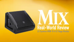
LD Systems recently released the Mon 10 A G3 floor wedge, and we put it through the paces to see how it performed.
Techivation has launched AI-Loudener, a new AI-powered audio plug-in for adding loudness, harmonic excitement, and warmth.
Nugen Audio has announced its new Halo Suite for immersive mixing projects, which includes Halo Vision, Halo Upmix and Halo Downmix.
Telos Alliance has introduced the company’s latest series of television audio processors, the Linear Acoustic AERO.20, AERO.200 and AERO.2400, which will all be featured...
Nembrini Audio has introduced its new Bass Hammer plug-in, designed with bass tone sculpting in mind.
Penteo Audio Plugins has released Penteo version 6, which adds 15 new creative workflow controls and presets.
Universal Audio just released two native plug-ins this week—Verve Analog Machines and Verve Analog Machines Essentials.

Solid State Logic will debut System T Cloud, a comprehensive virtualized audio mixing solution for live-to-air broadcast, at NAB.
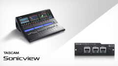
TEAC Corporation will launch the Tascam IF-ST2110 expansion card at the 2024 NAB Show, enabling SMPTE ST 2110 networking on Sonicview mixing consoles.
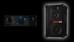
Eleven Engineering has introduced its new Electrotec Audio Stage One wireless portable speaker through a Kickstarter campaign.
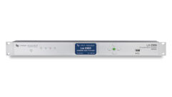
Telos Alliance is adding Dolby Digital Plus with Atmos encoding to the company’s Linear Acoustic LA-5300 broadcast audio processor.
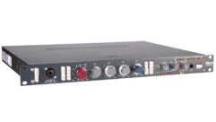
Neve has launched its new 1073SPX-D, a combination 1073 preamp and digital audio interface with USB and ADAT connectivity.
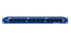
Radial Engineering has shipped its new Catapult Rack TX and Catapult Rack RX units first announced at the NAMM Show in January.
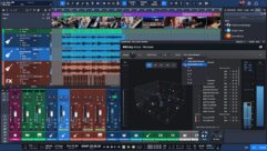
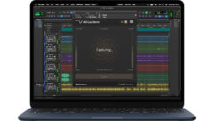
PreSonus Studio One 6.6 offers native Apple Spatial Audio monitoring within its Dolby Atmos renderer, plus other new features.
Solid State Logic will showcase its new Control App (TCA), a virtualized control solution, at the NAB Show.
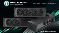
Neutrik Americas has introduced three new interfaces for connecting legacy audio gear to modern Audinate Dante networks.
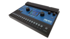
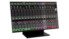
Aviom has updated its A640 Personal Mixer with a firmware download that adds a variety of new features.
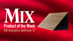
New from GIK Acoustics is the latest addition to the SlatFusor Series of acoustic treatments, the SlatFusor CT.
We asked London/Belgium-based engineer Wes Maebe to spend an imaginary $100,000 outfitting an imaginary studio. The place may not exist, but it sounds awesome!
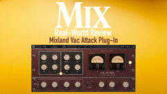
Find out why our reviewer calls the Mixland Vac Attack "a monster" for its ability to emulate lush tube circuitry.

The Mix review team puts the Lauten Audio Snare Mic to the test in the studio for a Real-World Review.
We asked London/Belgium-based engineer Wes Maebe to spend an imaginary $100,000 outfitting an imaginary studio. The place may not exist, but it sounds awesome!
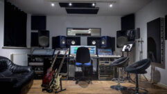
We asked London/Belgium-based engineer Wes Maebe to spend an imaginary $100,000 outfitting an imaginary studio. The place may not exist, but it sounds awesome!
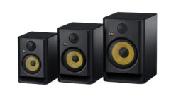
KRK brings a new tweeter design, multiple DSP voicing modes and a refreshed LCD to the ROKIT line.
The JBL Pro Connect app gets a V2 overhaul with Demo Mode, Full Screen Mode, Snapshot Language Support and more.
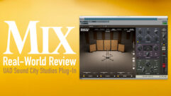
A new UAD plug-in lets you transform your recordings with the acoustics and mics from an iconic studio—so we put it to the test.
The Three-Body Technology (TBT) Cenozoix Compressor is a new, comprehensive plug-in with a whopping 24 different compressor styles.